 |
 |
8 Cylinder Konig Engine
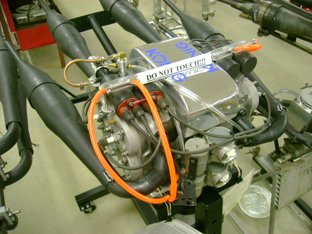 |
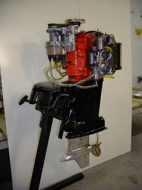
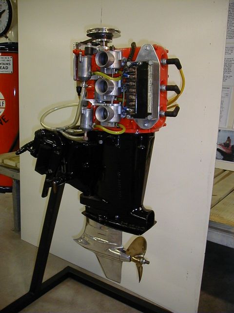
This 8-cylinder Konig is a one-of-a-kind motor built by Marshall Grant from a powerhead originally engineered for racing motorcycles with side cars. It consists of 2 flat, counter-rotating 500cc rotary valve 4-cylinder engines placed back-to-back and geared through a specially made Konig lower unit. It was driven for Marshall Grant by drivers Charlie Bailey and then Dan Kirts. It was estimated at a maximum speed of 130 mph. The 8 cylinder Konig was first run at Lakeland, Florida, in 1974 with Charlie Bailey driving for Marshall Grant. Marshall later sold the engine to Joe Michelini.
|
1928 Caille Model 30 Racer
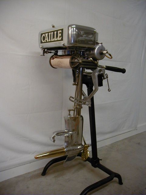 |
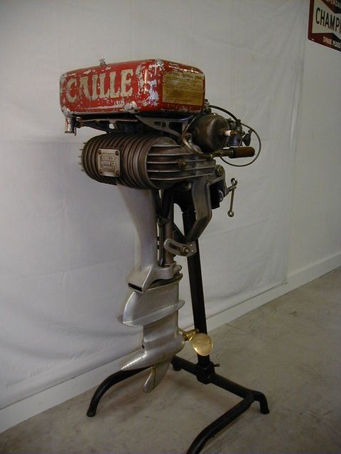
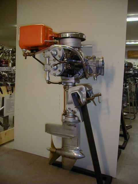
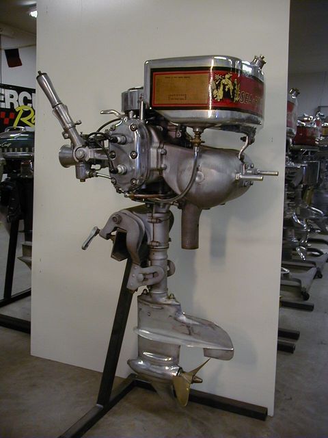
1928 Caille Model 30 Racer
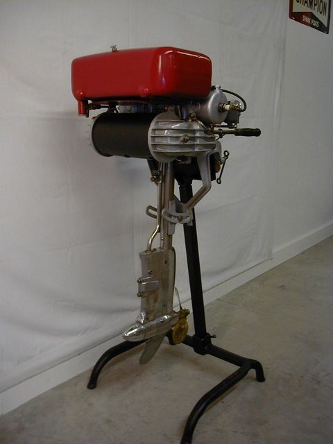
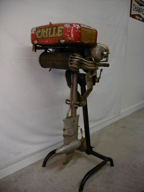
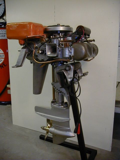
This motor was the first uniquely designated racing model introduced by the Caille Perfection Company of Detroit, Michigan. It was a class “B” motor (19.6 cubic inches in displacement) and has unique features like two auxilliary air valves in the intake manifold to allow racers to increase total airflow into the motor when running at speed, a sliding exhaust back-pressure relief valve on the underside of each exhaust manifold, optional spark plug locations in the ends of the cylinders to decrease charge burn time (and thereby achieve greater combustion pressures) and a “convertible” lower unit to enable running with either a pusher or puller-style propeller (the latter was deemed more appropriate for racing). It was felt that a puller-style propeller out in front of the lower unit (which was typically referred to as a “tractor” configuration) would have more “bite” in the undisturbed water and thereby offer more potential for speed. The thinking was correct but there was an attendant downside… when cornering with a tractor lower unit, the water turbulence over the lower unit causes boat instability in the corners and thereby necessitated reduced cornering speeds. The net result was what you gained in the straight-aways, you typically lost in the corners.
This motor was found with the unusually long rear cone on the lower unit. The motor is actually a mix of Model 20 (Caille Master Twin) and Model 30 components. It is conceivable that this motor was a factory prototype that was built in an attempt to further streamline water flow over the lower unit and thereby reduce cornering instability. No other such motors with a long rear gearcase cone are known to exist so it is probable that the experiment was unsuccessful.
Other details on the motor include:
This model 30 was typically delivered with spark plugs mounted in the tops of the cylinders and with a 3-blade “pusher-style” propeller (optional 2-blade “puller-style” racing propellers were available in 3 different diameter & pitch combinations)
Exhaust manifold heated intake air
Magneto ignition
3rd port intake mixture valving
Sleeve bearings throughout
Piston-type water pump
The history on this motor is unknown.
|
1928 Caille Model 30 Racer (2)
 |
2nd photo
|
1929 Caille Model 36 Flash Racer
 |
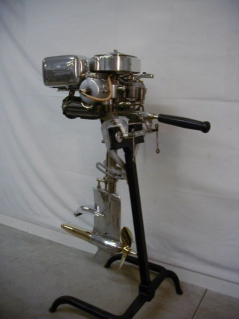
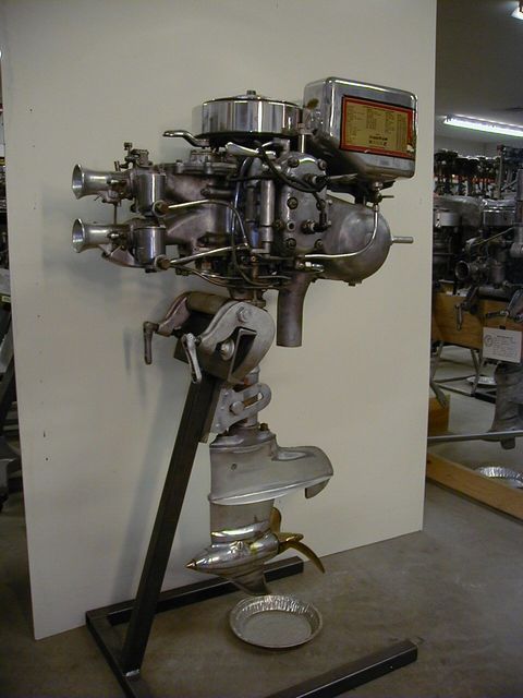
1929 Caille Model 36 “Flash Racer”
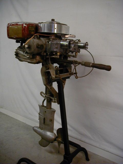
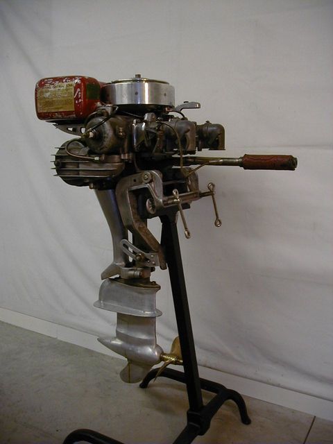
This motor is an evolution of the class “B” Model 30 Racer. It is the little brother to the Model 46 “Streak Racer” and the pair were advertised as the “Lightning Twins”. Improvements over the Model 30 include:
Dual Tillotson carburetors which are simultaneously opened and controlled by a twist-grip throttle on the tiller arm
14:24 lower unit gear ratio
Coolant circulation induced by propeller wash (no water pump and improved water pick-up for less drag)
Larger exhaust manifold for less exhaust restriction
Elimination of auxiliary air valves and exhaust back-pressure relief valves
Use of air-horns to eliminate heated intake air
Ball bearings on prop shaft
The history on this motor is unknown.
|
1929 Caille Model 36 Flash Racer (2)
 |
2nd photo
|
1929 Caille Model 46 Streak Racer
 |
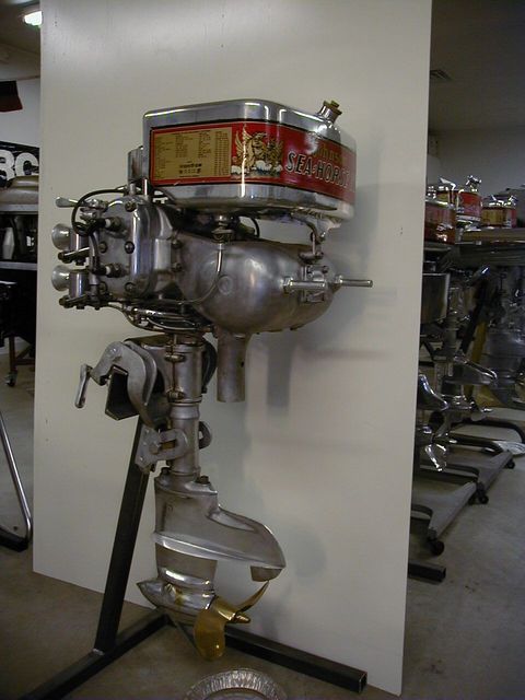
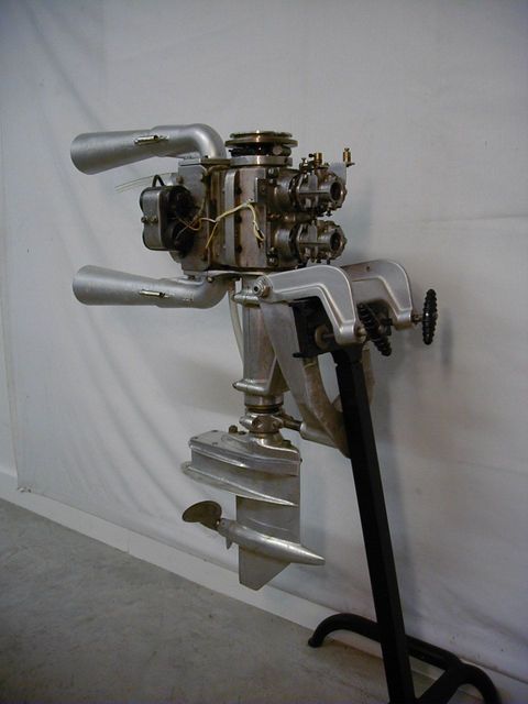
1929 Caille Model 46 “Streak Racer”
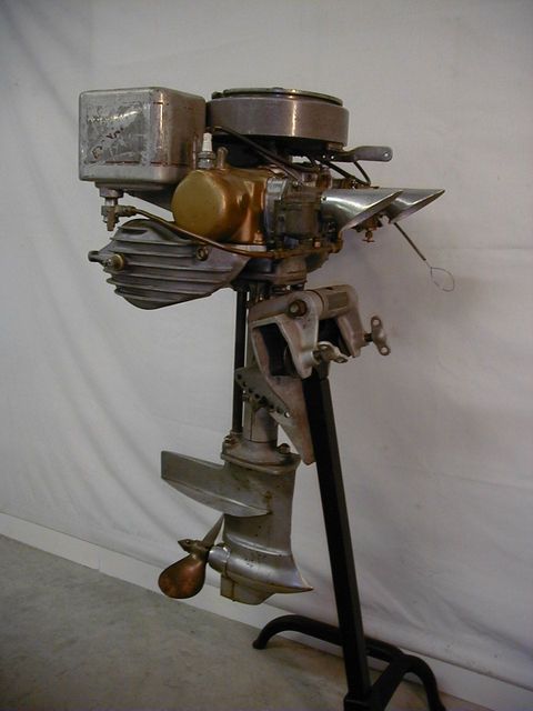
This 29.6 cubic inch class “C” motor is the bigger of the Caille “Lightning Twins” and is very similar in features to it’s little brother, the Model 36 “Flash Racer”. It too is a 3rd port motor with dual carbs, air horns (no heated air), sleeve-type motor bearings, twist-grip throttle control, magneto ignition, large exhaust muffler, coolant recirculation via prop wash, tractor lower unit, ball bearings on prop shaft and 2-blade propeller. The gear ratio is 14:20.
The history of this motor is unknown.
|
1929 Caille Model 46 Streak Racer (2)
 |
2nd photo
|
1931 Caille Model 40 Red Head Racer
 |
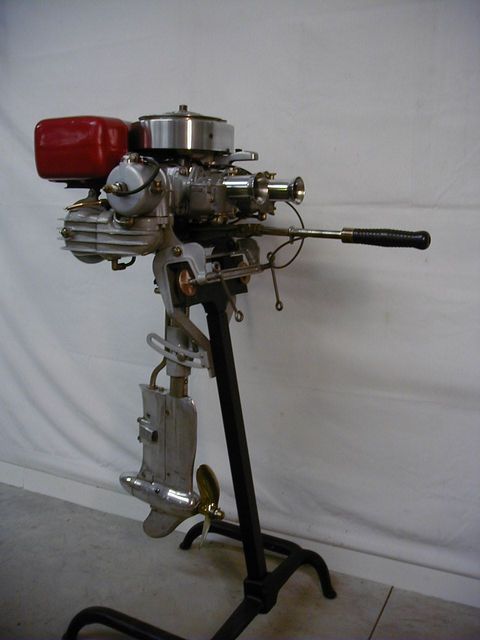
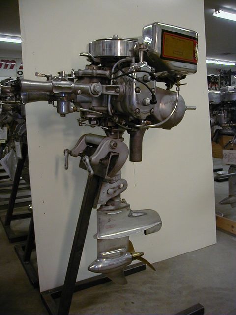
1931 Caille Model 40 “Red Head” Racer
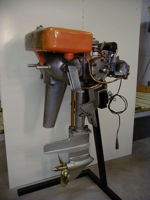
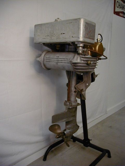
This 19.6 cubic inch class “B” motor is an evolution of the Model 36 “Flash Racer”. In 1930, some Caille Models received red-colored tanks with a large decal on top that featured a red-headed girl with her hair flowing in the wind… hence the name “Red Head”. The biggest changes in the motor was the use of low friction bearings in the powerhead (ball-type main bearings and roller-type bearings on the large ends of the connecting rods). It also incorporated a more streamlined lower unit design with a centrifugal-type water pump. The lower unit gear ratio was revised to 13:22. The motor is equipped with the regular production down-turned air-horns that feature integral chokes (straight, flared air-horns were an option).
The history of this motor is unknown except that it was found in Wisconsin.
|
1931 Caille Model 40 Red Head Racer (2)
 |
2nd photo
|
1966 Crescent C Alky Racer
 |
1966 Crescent C Alky Racer
This 3-cylinder in-line racing motor was manufactured from the mid-1960s to the early 1970s by a Swedish company with exceptional talent in 2-cycle racing engine technology. These motors were imported by Dick O’Dea, a noted race engine builder and outboard racer from New Jersey. Principally because of its free-breathing loop-scavenged combustion process and cross-pulse internal exhaust tuning, the Crescent C was significantly faster than the domestic class C motor of choice, the Mercury Mark 30H. Other features that contributed to its stellar performance were an assembled crankshaft, one-piece connecting rods, no water pump, flat top pistons and triple carburetors. The tower housing contained an easily changed exhaust tuning pipe that was available in two lengths for long or short race courses. The tuning was so effective that efforts to further improve the tuning with external pipes typically resulted in lost power. Intake valving was done with a 3rd port arrangement. The motor has a belt-driven distributor and battery ignition. There were no iron or steel liners in the aluminum block, but the cylinder bores were chrome plated. Unfortunately, poor plating quality turned out to be the Achilles heel of this motor. In time, most of these motors self-destructed when the bore plating started to flake off. But while they were running well, no other class C motors could equal them. The lower unit used a 13:14 set of gears.
Because of the extreme disparity in boat speeds between the Mercury and Crescent racing motors, the APBA was faced with a dilemma on what to do with the Crescent motor in regard to stock class C racing. After much deliberation, they created a unique stock class (“Super C”) for the Crescents in the early 1970s. Usage in the alky classes was a different story… the Crescents dominated the C-alky classes from the onset.
This particular motor was owned by Dick O’Dea and was built with special Konig carburetors for its intended use with alcohol. It was originally raced by John Schubert in the C-Alky Hydro class in 1966 and 1967. It won the Division 1 Championship in 1967. The motor was later raced by Dick O’Dea and John Yale, and the latter used it in an attempt to set a one-kilometer speed record at Norristown, NJ. On the first leg, John Yale went through the traps at 113 mph, which was well above the existing class C speed record. However, on the return leg, the hydro blew over and John woke up in the hospital. No further speed record attempts were made with this motor but the speed potential of the Crescent C-Alky motor was clearly evident.
Crescent was subsequently bought out by the Swedish automobile maker Volvo, primarily to access the 2-cycle racing technology for possible automotive racing applications. Due to dwindling internal interest in outboard racing motors, Crescent C production was terminated. However, the outboard line for commercial and pleasure-craft usage was retained and became the Volvo-Penta brand.
|
1966 Crescent C Alky Racer (2)
 |
2nd Photo
|
1930 OMC Model 176 Speedy Bee Racer
 |
1930 OMC Model 176 Speedy-Bee Racer
This motor is, without a doubt, one of the most revolutionary and amazing racing engines to ever come out of the American outboard motor industry and, as such, is the rarest of the OMC racers. Not only was it the first domestic motor to achieve one horsepower per cubic inch of displacement, but it was done 1930 when motors were still pretty much in their formative years. It was way ahead of its time and nothing in class “B” could compete with it, not even the highly successful Johnson SR. The complicated design and necessary attention-to-detail provided at the factory (they were literally “hand-built”) resulted in a cost that was way beyond the means of most racers. Unfortunately, it arrived at a point in history (at the start of the Great Depression) when people had little money available for discretionary spending, despite the growing popularity of outboard racing. Thus, OMC had no choice but to limit production, price the motor at a loss (even at $400 it was still a very expensive motor) and write the project off as an “image-maker”. Only about two dozen motors were produced and very few survive today because of the typically tortuous use by racers and the unavailability of replacement parts. It is especially rare to see one like this (serial number 6) that is essentially complete and could be put in running order with very little effort.
The Speedy-Bee motor was created by Finn T. Irgens, the Chief Engineer of OMC when the motor was introduced. Irgens notable career included the positions of Chief Engineer at both Johnson and Lockwood before he came to OMC as part of the Lockwood purchase. Its revolutionary design features were protected under two patents granted to Irgens.
They included:
Dual rotary valves with very smooth-flowing intake paths into the crankcase
Dual carburetors with rotary throttles, synchronized cable controls and built-in accommodations (i.e., bowden wire connections) for use with a “dead-man” throttle
Six-bolt cylinder heads for better sealing
Large, free-flowing ports with aggressive timing
Modern bearings (ball and roller) with a pressure-fed lubrication system to ensure availability of oil at key points (oil mixed with the fuel was considered as “supplemental”)
Battery ignition to reduce flywheel weight and improve startability
Built-in “steering bar”
Dual feed lines from fuel tank… one to each carburetor
Engine exhausted into muffler with relief valve to facilitate starting
Streamlined lower unit with no water-pump for reduced parasitic losses (coolant flow was entirely dependent on forward motion of the motor through the water… the motor could not be “idled” or it would burn up)… water pick-up was on underside of cavitation plate
Ball bearings in lower unit… 13:22 gear ratio
The motor came with no warranty or owner’s manual. A buyer only received a three page set of instructions. Although the information alludes to covers over the carburetors (probably to help prevent water intrusion)… actual parts or pictures of them are not known to exist.
The biggest downsides of the motor are its weight (110 pounds) and the lack of good places to grasp the motor when lifting it. Unfortunately, many of the ancillary parts (e.g., carburetor air horns, oil tank, carburetor fuel level balance tube, etc.) are fragile and are easily broken or damaged if the motor is lifted by these parts or dropped. That probably explains why you see damage to those parts on this motor.
The racing history of this motor is unknown.
|
1930 OMC Model 176 Speedy Bee Racer (2)
 |
2nd photo
|
1930 Evinrude Model 177 Speeditwin
 |
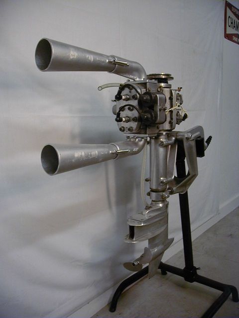
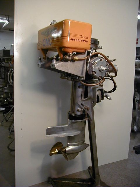
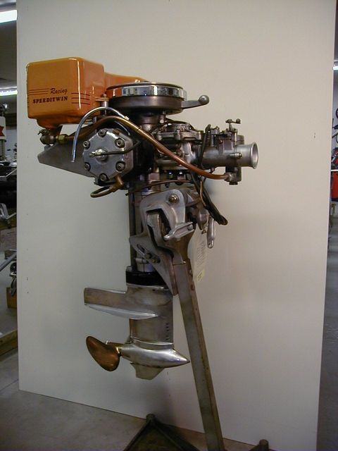
1930 Evinrude Model 177 "Speeditwin Racer”
In prior years the Speeditwin 3rd port motor was just offered as a service model. For 1930, OMC introduced a racing model with either single or dual carburetors with a streamlined gear foot and shortened tower. Battery ignition and a light flywheel were not offered. The single carb version used a cast aluminum manifold to span 3rd-port entries into the cylinders, whereas the dual carb version had short aluminum manifolds between the carbs and cylinders. Throttle control on the dual carb version was offered in two arrangements, both of which provided synchronized opening of the throttle plates. One was a rigid bail between the two Tillotson carburetor throttle levers and the other was a more complicated bowden wire linkage. Stylish straight air horns gave the dual carb version a very distinctive look. The motor was exhausted through a large muffler. The powerhead bearings were unchanged from the service version (sleeve type throughout). However, ball bearings were utilized in the lower unit. The motor was cooled by a water pump at the top of the lower unit with the pick-up on the underside of the cavitation plate ahead of the propeller. Performance was not advertised but peak horsepower was achieved at 5000 rpm.
This particular motor has the dual carb arrangement with the progressive linkage. The lower unit is not the original but old racing motors often have substitute parts to make up for the lack of correct parts. This particular unit has a 13:22 gear ratio and has a two-blade bronze propeller. The motor’s racing history is unknown but it must have seen some severe duty because of major repairs on the lower unit.
|
1930 Evinrude Model 177Speeditwin Racer (2)
 |
2nd photo
|
1930 Evinrude Model 178 Four Sixty Racer
 |
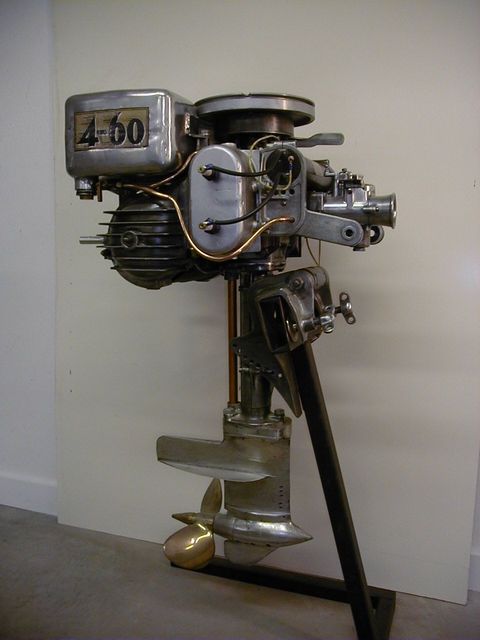
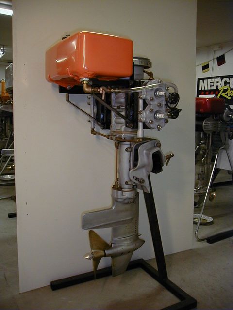
1930 Evinrude Model 178 “Four-Sixty Racer”
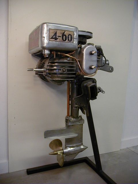
This motor is the grand-daddy of the Class “F” racers. Its name is derived from the four cylinders and 60 cubic inch displacement. It is an “opposed” engine with two rotary valves in the center of the crank (one for feeding the top cylinders and the other for feeding the bottom). Ball and roller bearings are used on the mains and rollers and needles are used on the big and small ends of the rods, respectively. It was originally sold with a large muffler but most of these were discarded when racing to reduce exhaust backpressure. Battery ignition was used for ease of starting and to enable the use of a smaller flywheel (to reduce rotational inertia). The large ports were free-flowing and aggressively timed. Its performance on gasoline was never advertised but peak horsepower was achieved at 5000 rpm. Many of the old racers used methanol as a fuel to increase performance but because the cylinder heads on this motor were integral to the cylinder blocks, it was difficult to raise the compression ratio to take full advantage of the alcohol fuel. OMC realized the shortcomings of the integral cylinder heads and later brought out “detachable” cylinder heads to make it much easier to modify combustion chamber volumes. The carburetor is a Vacturi Model A-500. The short tower and streamlined lower unit has low-friction bearings on both drive and propeller shafts as well as a water pump with a pick-up on the front of the lower unit, above the gearcase. Two-blade bronze racing propellers were offered by OMC as well as the after-market. One of the best attributes of the 4-60 was its durability, and this often enabled racing victories when vying against faster but less durable competitors. The 4-60 racers were manufactured and sold up to WWII. Because of their longevity and the efforts of after-market parts suppliers, they were used for many years after the war.
This particular motor does not have the correct lower unit. However, it probably was raced with this 13:22 gear ratio unit and 2-blade propeller. The racing history of this motor is unknown.
|
1930 Evinrude Model 178 Four Sixty Racer (2)
 |
2nd photo
|
1939 Evinrude Model 4328 Midget Racer
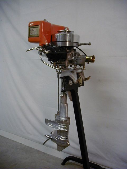 |
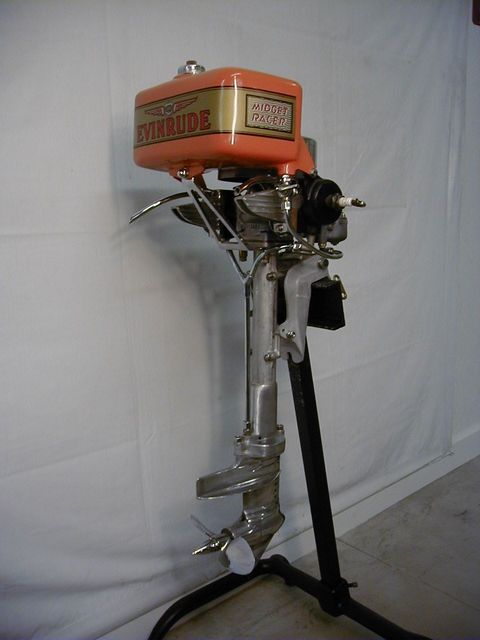
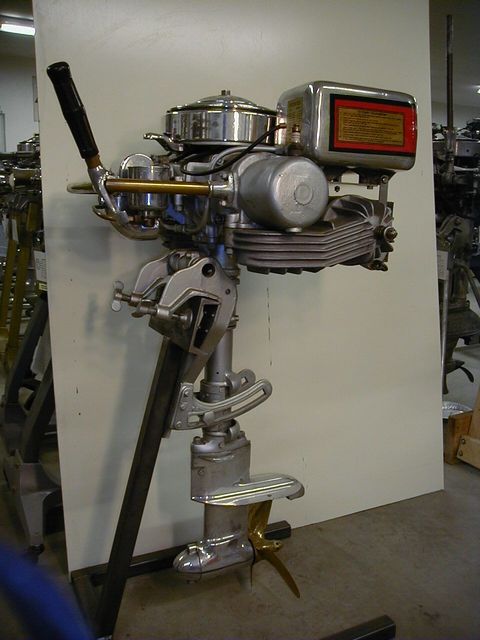
1939 Evinrude Model 4328 “Midget Racer”
This diminutive class M motor had a displacement of 7.44 cubic inches and was typically run on methanol and castor oil. It could reach speeds of over 40 mph on a small hydroplane with a lightweight driver. The original Midget was introduced in 1933 as a Model 454. It was priced at $125.00 and weighed a mere 38 pounds. The last model (4328) was sold from 1939 to 1941. The motor is an opposed twin with sleeve bearings and a rotary valve on the bottom of the crankshaft. A Tillotson carburetor and magneto ignition were used along with a short tower, streamlined lower unit with a 13:20 gear ratio and a tiny two-blade propeller. A centrifugal water pump was located at the top of the lower unit and the water pick-up was on the front of the lower unit, above the gearcase. The horsepower peaked around 5000 rpm. OMC reportedly gave away Midget Racers as door-prizes at some major races to further interest in the sport as well as in their brands. Unfortunately, the lack of low friction bearings made the motors somewhat susceptible to throwing rods so these motors are relatively scarce today.
The racing history on this motor is unknown.
|
1939 Evinrude Model 4328 Midget Racer(2)
 |
2nd photo
|
1934 Evinrude Model 8001 X Racer
 |
1934 Evinrude Model 8001 “X” Racer
This motor was created exclusively for international class X (one liter displacement) outboard racing. Because the 4-60 racer admittedly had limited breathing capability, a “skunk works” project at OMC was initiated to try adding rotary valves at the top and bottom of the crank to supplement the flow through the original rotary valves in the center of the crank. A secondary objective was to maximize the displacement at just under 60 cubic inches but a design error was made and the new set of crankshaft throw blocks produced a stroke that exceeded the allowable limit. Hence, the crank was unusable in the 4-60. However, because there was a public demand for something more competitive than the 4-60 in international racing and because the new crank was usable in a one-liter displacement application in conjunction with the standard 4-60 bore, OMC authorized manufacture of the Evinrude X… albeit for only one year (due to lingering effects of the Great Depression).
The most significant changes from the 4-60 were the new crankcase and crankshaft. Due to the rarity of these motors (reportedly, only 25 to 50 of them were produced and about half were used in Midget car racing) and the limited amount of information published on the “X”, there is a lot of controversy over what other components were actually changed. This motor was found with unique pistons (a slightly different deflector shape) and two unique cylinder heads (the latter are each clearly stamped with an “X”). The heads on the opposite side are standard 4-60 parts but were modified for compatibility with the unique piston deflector shape. The unique heads and pistons could well be original “X” parts. The carburetor is a large Tillotson model with a primer pump that injects fuel into both upper and lower crankcase cavities for cold starting. The battery ignition system utilizes a unique stator plate largely for compatibility with the aforementioned revisions to the top of the crankcase. The coils and coil brackets are totally different from the 4-60 in that the coils are smaller and mount on an “X” shaped bracket on the port side of the motor in front of the cylinders. It is not known whether the tower and lower unit are original. The gears in this motor have a 13:19 ratio and a 2-blade bronze propeller is utilized. The “X” motor was a much better performer than the 4-60 but it had one major fatal flaw. The proper rotary valve clearances were absolutely critical and very difficult to set up. With any appreciable wear, the motor became very hard to start and would not perform well.
|
1934 Evinrude Model 8001 X Racer (2)
 |
2nd photo
|
1930 Johnson VR50 Racer
 |
1930 Johnson VR-50 Racer
The class “D” (40 cubic inch) 1929 VR-45 was Johnson’s first opposed 4-cylinder racer. It was introduced simultaneously with the class “B” SR-45 and, in essence, was the equivalent of two SR-45’s stacked on top of one another. It had an external rotary valve that turned at crankshaft speed and was fed by a single Johnson barrel-type carburetor. Its only real competition was the 1928 Elto Hi-Speed Quad. While the high torque VR was faster, Johnson was interested in increasing its performance. For 1930, they introduced the VR-50 which was a twin barrel-carb version of the same basic motor to achieve the desired performance improvement. Interestingly, it also had half-speed rotary valves which offered improved durability with no negative effect on performance. Other features of the VR-50 included magneto ignition, compression release to make starting easier, large muffler with a single pipe outlet (above water), short tower and steamlined gearfoot with a 12:21 gear ratio. No water pump was used… Johnson relied on a “prop wash” to induce coolant flow… the water pick-up was on the underside of the cavitation plate. Unfortunately, the motor had two major problems. The first was that the twin carbs were very difficult to adjust while bouncing around in a racing boat. The second was that the crankshaft and connecting rods were under-designed such that many of these motors self-destructed (i.e., broken cranks and tossed rods) when run hard at high speeds. Johnson addressed the first issue by switching back to a single carb (Vacturi AO500) and half-speed rotary valve for 1931. The rod and crank issues could not be resolved without a total redesign, which was out of the question because the Great Depression made investment dollars very tight and prospects for selling many of these relatively expensive motors very dim. Thus, racers typically retro-fitted VR-50 motors with the 1931 crankcase, rotary valve and carburetor (when they became available) but had to live with the durability issue. Many of the dual carb hardware sets that were removed were simply discarded so finding a motor today with such hardware and without crank and rod issues is very rare, indeed. That’s a shame because a complete VR-50 is an impressive sight!
The racing history of this motor is unknown.
|
1930 Johnson VR50 Racer (2)
 |
2nd photo
|
1931 Johnson XR55 Racer
 |
1931 Johnson XR-55 Racer
When OMC introduced their Model 178 “Four-Sixty” in 1930, it had no serious competition and consequently was very successful in class “F” outboard racing. Johnson’s largest motor was the 40 cubic inch VR-50 but it wasn’t a viable competitor because of its displacement disadvantage. Because of the Great Depression, Johnson’s only option was to enlarge the VR bore to the maximum and hope it would compete. The result was the 50 cubic inch XR-55. With the high revving capability enabled by its rotary valve, the XR could actually outperform a 4-60 in spite of spotting it 10 cubic inches. Unfortunately, the same crankshaft and connecting rod frailty seen in the VR also showed up in the XR… only to a much greater degree. These motors usually failed to complete races without self-destructing. This became evident in the very first races in which the XR competed and Johnson cancelled all further production of this model shortly thereafter. Actual production records are not available but, reportedly, only a few dozen XRs were made. With the limited number produced and the extremely high attrition rate, the XR-55 is undoubtedly the rarest of the Johnson racers.
The racing history of this motor is unknown.
|
1931 Johnson XR55 Racer (2)
 |
2nd photo
|
1965 Harrison A Racer
 |
1965 Harrison “A” Racer
This motor was manufactured by Birmingham Metal Products in Birmingham, Ohio. It was the brainchild of Milford Harrison and essentially is an evolution of the British Anzani racer with changes to make it both more durable and more competitive. The loop-scavenged, alcohol-burning design is an alternate firing twin with two carburetors and reeds on the front of the crankcase and a single side-mounted carburetor connected to an internal rotary valve. The throttle action is progressive in that the side carb throttle opening is delayed until the front carbs are very nearly at full throttle. Other features include battery ignition and tuned exhaust megaphones. This particular motor has a Harrison tower and an Anzani lower unit with a 1:1 gear ratio (Harrison did offer their own improved lower unit design as an option). There is no water pump. Coolant flow is induced by forward motion of the boat… the water pick-up is on the underside of the gearcase nosecone.
The racing history on this motor is unknown.
|
1965 Harrison A Racer (2)
 |
2nd photo
|
1939 Evinrude Hex Head Racer
 |
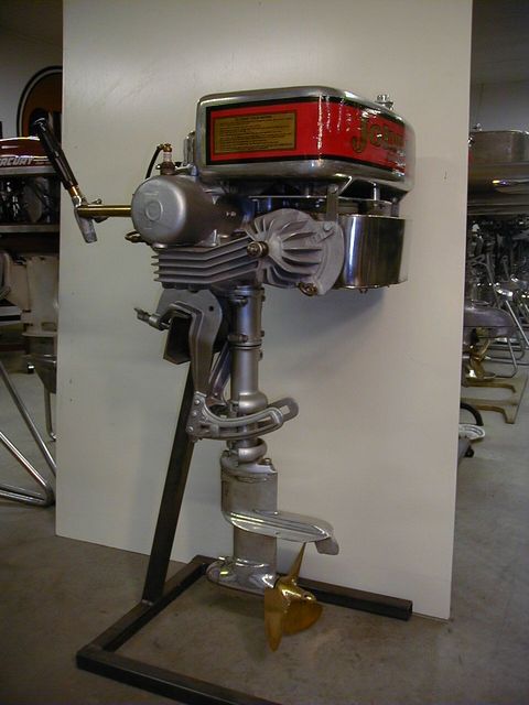
1939 Evinrude Model 6042 “Hex-Head Racer”
This 30 cubic inch opposed twin class “C” motor was the final evolution of the Speeditwin racer from OMC and essentially consisted of the best racing technologies from the OMC stable at that time. It used the six-bolt cylinder heads that were first used on the Speedy-Bee, external rotary valve from Johnson, low friction bearings in the powerhead and lower unit and streamlined lower unit from Evinrude. The basic concept was originally introduced in the prior year as the Model 6038 but inherent cooling problems quickly led to the better-cooling, hexagonal cylinder heads (obviously, the name of the motor was taken from the distinctive-looking heads). Other features included battery ignition with a light flywheel, centrifugal water pump for cooling with the pick-up on the front of the lower unit above the gearcase, open exhaust with heat deflectors and a 13:19 lower unit gear ratio. The motor was originally priced at $395.00 and weighed 105 pounds.
This particular motor has the serial number one ID plate and belonged to and was raced by the Raun family in California. They had requested the first production Hex Head motor in a letter to Evinrude and noted that they had long been good Evinrude customers. To their surprise, Evinrude fulfilled their request. At some point during its racing days, the motor tossed a rod and the crankcase was replaced. The original crankcase (still showing the stamped #1 serial number) has since been found in the same general area in California and was repaired and built into another Hex-Head motor. The two “#1” motors were reunited and displayed together at an AOMCI Constantine Super Meet a few years ago.
|
1939 Evinrude Hex Head Racer (2)
 |
2nd photo
|
1928 Johnson Model TR40 Racer
 |
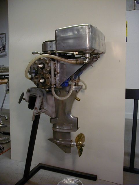
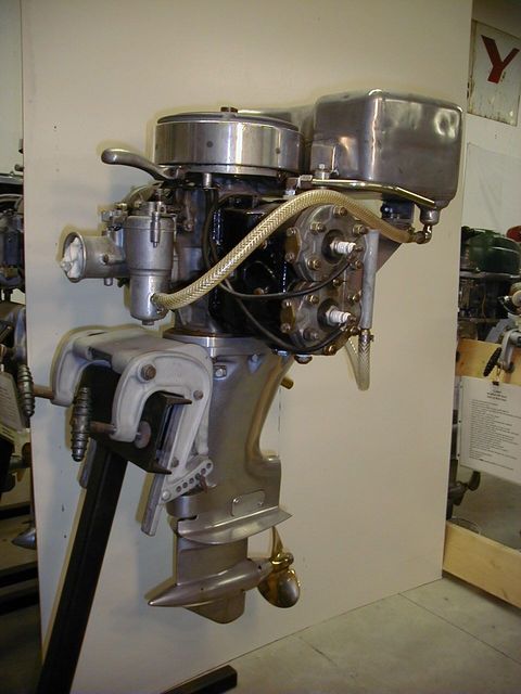
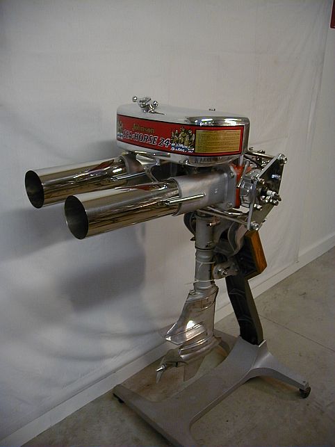
1928 Johnson Model TR-40 Racer
This behemoth (50 cubic inch displacement) is probably the biggest 2-cylinder outboard ever made. The design is the last example of Johnson’s original racing philosophy of beating its competitors by making bigger and more powerful motors. In 1926 they introduced the Model P-30, a 6 HP, 22.7 cubic inch opposed twin which literally dwarfed most everything offered by the competition. It essentially was a scaled-up version of the first Johnson outboard motor and succeeded in starting the outboard motor “horsepower war”. By 1928 water speeds had come a long way so Johnson scaled the same basic motor up again and came out with the TR-40 that put out 25.75 HP at 3500 rpm. Features included 3rd port induction, sleeve bearings throughout except for roller bearings on the crank-pins, magneto ignition, aluminum pistons, muffler with an exhaust backpressure relief valve to aid in starting, compression release to make it reasonably easy to rope over and a somewhat streamlined lower unit with a 3-blade propeller. The motor was cooled by prop wash that was picked up on the underside of the cavitation plate. Despite its large size, the motor weighed in at only 110 pounds. 1928 was the first year that Johnson offered uniquely-designated racing motors. The class “E” TR-40 was the big brother to two other siblings of the same basic design concept, the class “B” KR-40 and the class “C” PR-40. Interestingly, all three were all one-year motors as Johnson realized the need to build motors with higher rev-capability (largely through extensive use of low friction bearings and better breathing) to gain a competitive edge. Also interesting is that all subsequent KR models were downsized to fit into class “A”. Unfortunately, the TR-40 was not a very robust motor and was prone to crankshaft failures when pushed hard. Due to a high attrition rate, there are few TR-40s remaining today. The physical size of this motor is definitely its most impressive attribute.
The racing history of this motor is unknown.
|
1928 Johnson Model TR40 Racer (2)
 |
2nd photo
|
1960 Hubbell Free for All Racer
 |
1960 Hubbell Free-for-All Racer
Pep Hubbell was a visionary in that he foresaw the need for after-market outboard racing motors and then focused on supplying such products. The Free-for-All motor was but one motor in the broad Hubbell product line-up and it essentially is a “poor man’s 4-60”. Hubbell bought war surplus motors (in this case an Evinrude Big Four) and modified them to meet approved racing specs for port size and timing, rotary valve timing, compression ratio, etc. and then adapted them to some existing racing lower unit (in this case using a Hubbell-made adaptor plate on top of a Mercury Quicksilver class “D” tower and lower unit assembly). The result was a competitive class “F” motor at a reasonable price ($610 in 1960). The downside was that the Mercury lower unit did not hold up very well under the brutal torque of the modified Big Four powerhead… but they were fast while they lasted. The actual number produced is not known but they seem to be relatively scarce today… probably because of their high attrition rate.
The racing history of this motor is unknown.
|
1960 Hubbell Free for All Racer (2)
 |
2nd photo
|
1933 Johnson Model PR-65
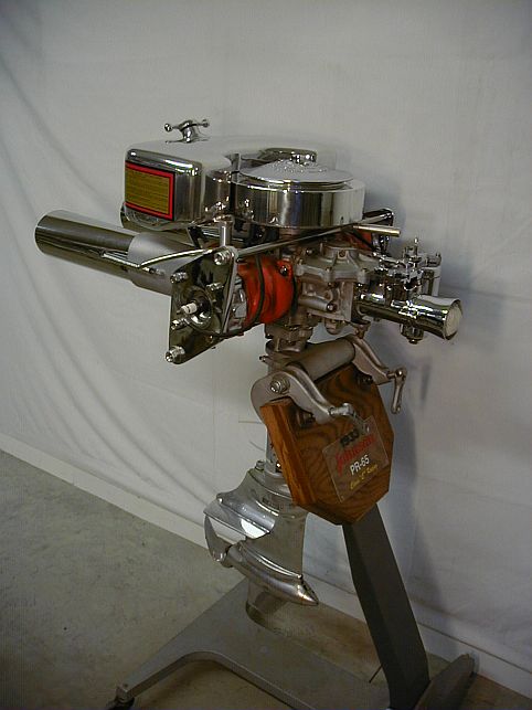 |
1933 Johnson Model PR-65
The PR is probably the most successful racer that Johnson has ever built, as evidenced by the fact that they are still being used today in antique racing events. It is a 30 cubic inch displacement class “C” opposed twin that was first introduced in 1930 as the PR-50 Model. That was the first year for Johnson’s half-speed external rotary valve, the most outstanding feature on the motor. In concept, the motor was much the same as the 1929 class “B” Model SR in that it had removable cylinder heads, muffled exhaust with a single pipe (above the water) outlet, short tower and nicely streamlined lower unit. Coolant flow was induced by prop wash into a pick-up on the underside of the cavitation plate. The PR gear ratio was 13:19. Unlike the Evinrudes, this serious racer used Magneto ignition and a heavy flywheel. The PRs were very fast and quite durable. Most racers removed the muffler and ran with the exhaust ports open to air. The motor’s most fragile component was the lower unit so many are found today with after-market versions. The only other design glitch was the use of the service engine outlet location on the port side of the fuel tank (a starboard outlet would have helped prevent fuel starvation on hard corners).
This motor has quite a pedigree. It was built by John Toprahanian, who was one of the most skilled and well-known antique race engine builders. The motor was owned and raced by Bud Tervo from Minnesota and reportedly did quite well on the racing circuit (Bud said he won a lot of races with this motor). It was found with a Wiseco lower unit and has since been restored by John Schubert. It now sports tuned exhaust stacks.
|
1933 Johnson Model PR-65
 |
1933 Johnson Model PR-65 (2nd photo)
|
John Deere Racer
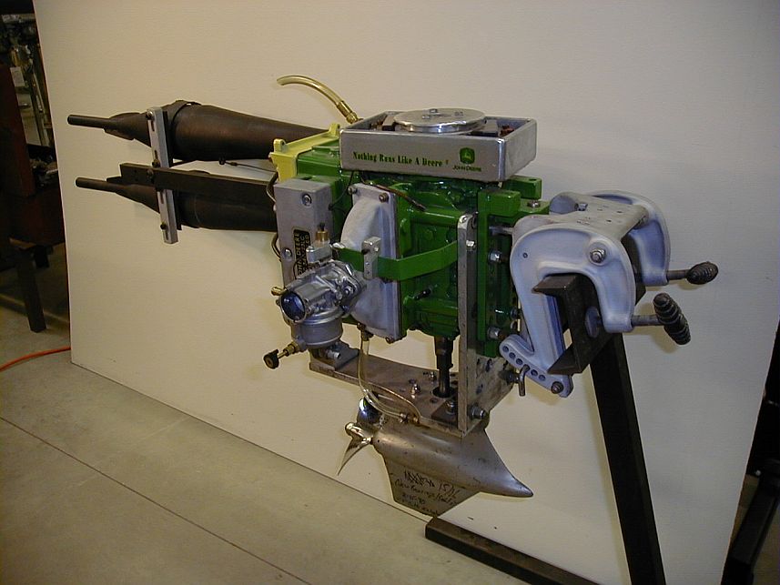 |
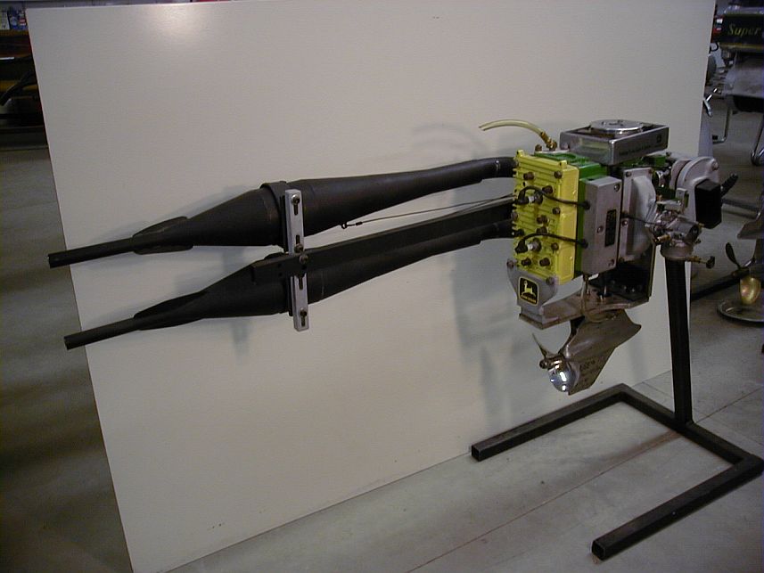
John Deere Racer
This alky motor was built by Keith Schictel of Kingsley, Michigan in 1976 for use in the APBA PRO “RB” class. The motor is an adaptation of a John Deere (Kioritz) 340cc “Liquifire” snowmobile engine. It was essentially a clone of the first John Deere racer that was built by Millard Peck of Karlin, Michigan. Keith’s version used Mercury clamp and swivel brackets and a fabricated aluminum frame that tied the powerhead to a Konig lower unit. Internal modifications were largely limited to raising the compression ratio and enlarging the exhaust ports. Based on class rules, the motor was limited to using a single floatless Carter Model N carburetor and a single expansion chamber. A later rule change enabled adding the second expansion chamber. Header pipes and sliding expansion chambers were fabricated. A Konig electronically-triggered battery ignition system was adapted to the top of the powerhead. There is no water pump. A water pick-up on the underside of the lower unit nose-cone provides coolant flow with forward motion of the boat. A 12:15 gear ratio was probably used for most of the racing with this motor but it now has a 15:16 set of gears.
This John Deere motors was raced for about 8 years by Keith and was extremely competitive until Konig finally surpassed it with the VB (rotary valve) motor. The John Deere was raced for a few years thereafter by the late Tom Squicciarini of Big Rapids, Michigan with limited success.
|
John Deere Racer
 |
John Deere Racer (2nd photo)
|
|
|


